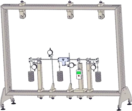
Experimental apparatus for comparing analytical and graphical methods to determine the elastic line of a beam
A single beam, loadable by a point force and — independently — by a pure bending moment, supported by any combination of clamp, articulated-with-force-gauge, and articulated-with-dial-gauge bearings. The apparatus is designed for one specific purpose: to let the student solve the same elastic-line problem by several different methods — the differential equation of the elastic line, the principle of virtual work, and Mohr's analogy (area-moment method) — and then verify each result against the measured deflection, slope and support reactions on a real beam.
Experiments
Determination of the elastic line of a beam by three different methods:
analytical integration of the elastic-line equation
principle of virtual work
Mohr's analogy (area-moment method)
Elastic lines for statically determinate and statically indeterminate beams
Application of the principle of superposition
Load cases: point load and pure bending moment
Determination of the maximum deflection and the angle of inclination of the beam
Experimental determination of the clamping moments on fixed supports
Comparison of calculated and measured values
Beam
Length1000 mm
Cross-section20 × 4 mm
Materialsteel
Quantity3 beams
Supports & loading
Clamp supports2 × clamp fixing, each with dial gauge to read the angle of inclination — switchable to articulated use
Force-gauge support1 × articulated with force gauge — reads the reaction directly for indeterminate cases
Moment generatordevice to apply a pure bending moment at an arbitrary point on the beam
Measurement
Support reactionforce gauge, ±50 N, graduation 1 N
Deflectiondial gauge, 0…20 mm, graduation 0.01 mm
Angle of inclinationdial gauge integrated into the clamp supports and moment generator
A complete set of experimental modules covering the core topics in strength of materials — elastic line, torsion, Euler buckling, frame deformation, plastic bending, and static equilibrium.