FM565 · Pipe Networks
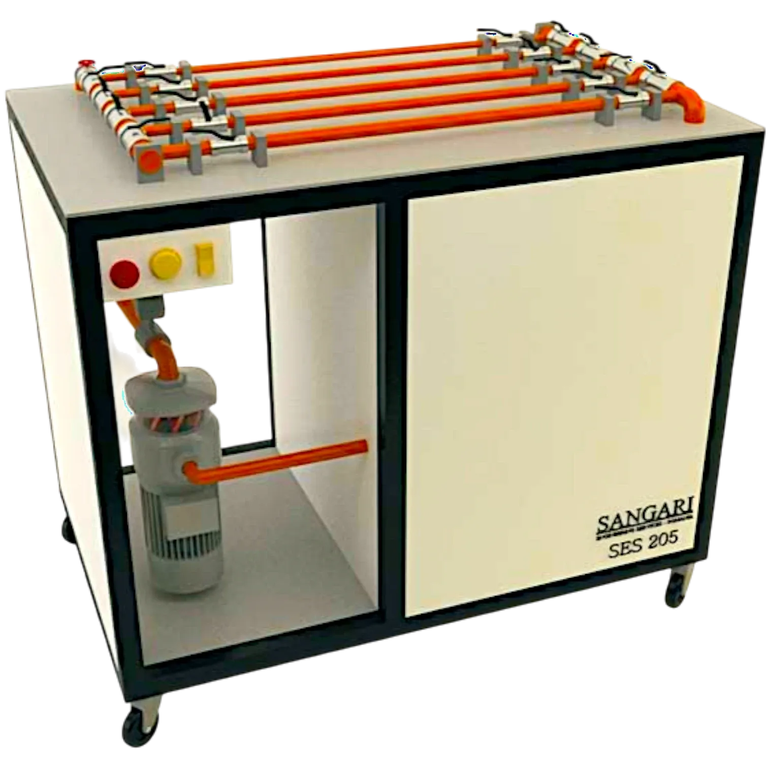
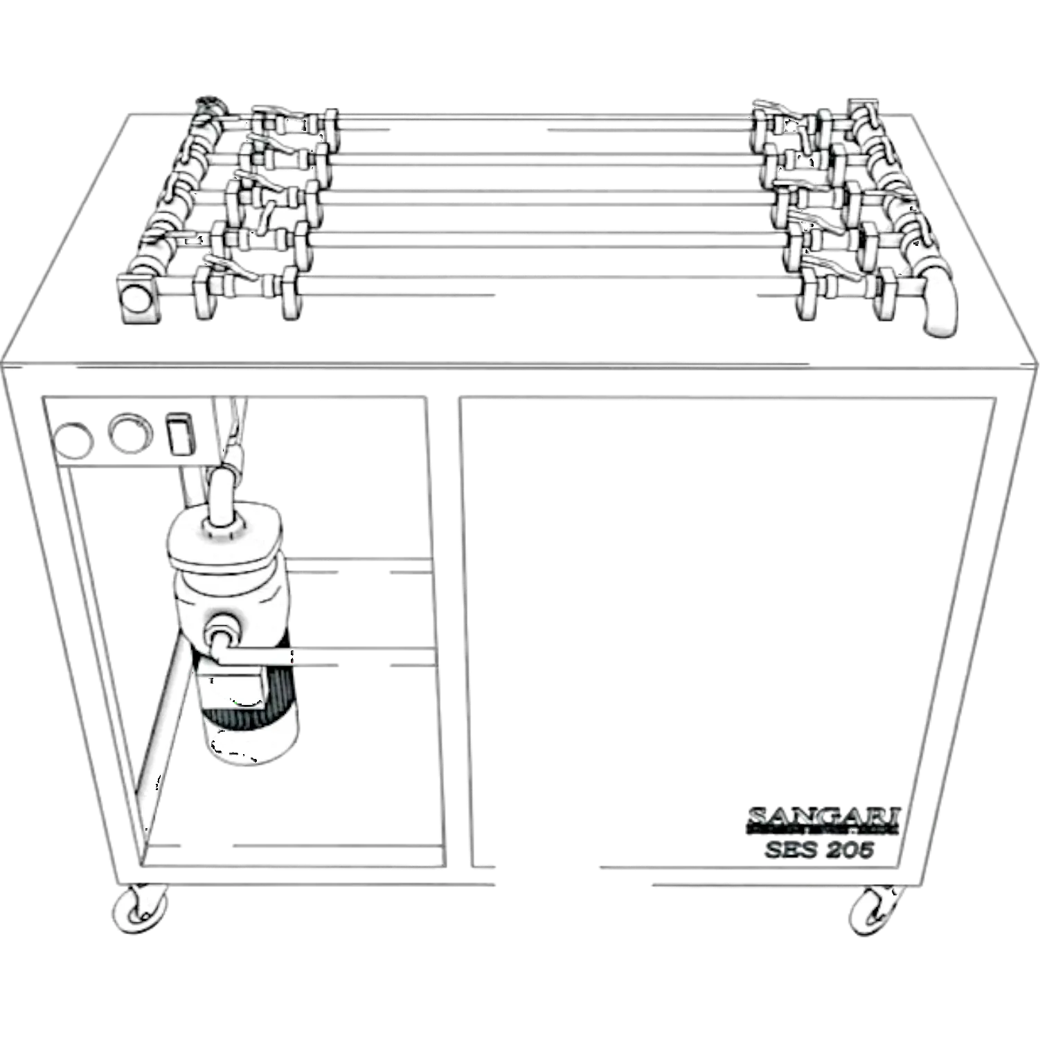
Schematic diagram of the FM565 apparatus — pipe networks
Five categories of hydraulic systems are studied:
Part of package
A comprehensive set of experimental equipment covering pipe flow hydrodynamics, pipe networks, water hammer, flowmetry, domestic water supply, and pipe maintenance.