All products

ST171 · Forces in a Crane Jib

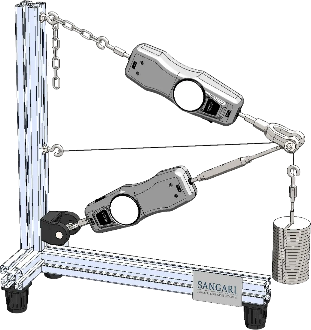
Experimental apparatus for the vectorial analysis of forces in a planar concurrent system — crane-jib model

A simplified model of a wall-mounted jib crane: a horizontal compression bar and a chain tie meet at the load-application point, where a calibrated weight is suspended. Spring balances integrated into each member read the tensile and compressive forces directly, letting the student compare the measured values against the result of a force parallelogram and an analytical solution. Because the geometry of both members is adjustable, the dependence of the bar forces on the jib geometry can be swept experimentally.
ST171 — Forces in a Crane Jib
Experiments
  • Graphical breakdown of forces by force parallelogram
  • Determination of the bar forces (tensile and compressive) for various jib geometries
  • Three-way comparison: measured — graphical — analytical
  • Influence of bar length and chain angle on the bar forces
  • Distinction between tensile members (chain) and compressive members (strut)
Apparatus
    Crane-jib model adjustable-length bar + chain tie, clamped to a vertical retaining column
    Retaining column stainless steel
    Base sturdy metal plate with transport handles
    Max applied load 50 N
Measurement
    Tensile spring balance 0…50 N, graduation 0.5 N (integrated into the chain member)
    Compressive spring balance 0…50 N, graduation 1 N (integrated into the bar)
Load set
    Weights 1 × 1 N hanger · 4 × 1 N · 1 × 5 N · 4 × 10 N
Delivery
  • Experimental unit — base plate, retaining column, jib bar, chain
  • 2 spring balances (1 tensile, 1 compressive)
  • Complete weight set
  • Storage case with foam inlay, instruction manual
L 600 H 620 W 200 mm
10 kg